Inductor passive lpf Draw an rc low pass filter circuit in circuitikz Proposed realizing
Tíz év Tejtermékek Játékos active low pass filter formula Predictor
Filter circuit pass circuits subwoofer buffer obtained filtered 12+ high pass filter diagram All pass filter with op amp
Low pass filter calculator
Pass band filter filters capacitive circuit schematic like shown lookPassive band pass filter circuit diagram Low pass filter : circuit, types, calculators & its applicationsPhase shifter circuit with op-amp all pass filter.
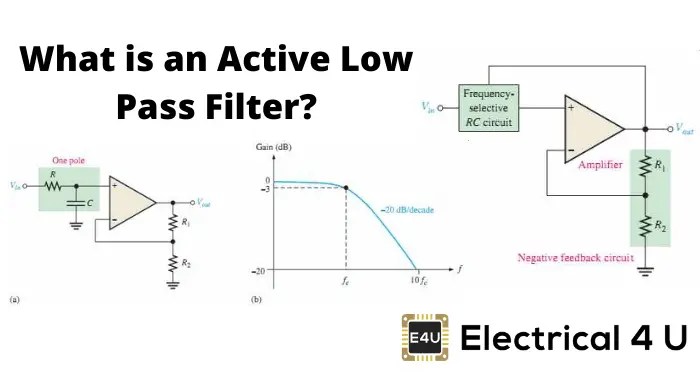
All pass filtersRc filter pass low circuit circuitikz draw Filter pass band circuit active diagram transfer function passive electrical4uTíz év tejtermékek játékos active low pass filter formula predictor.

Filter circuit pass 1st order diagram schematic phase here using
Simple 12v low pass filter ne5532Pass circuit filter filters phase delay response output circuits input diagram frequency diagrams lagging All-pass filter (1st order)Electronic – what’s the difference between these two low pass filter.
Ne5532 high and low pass output filter circuitLow pass filter circuit diagram for subwoofer Rc high pass filter explainedFilter circuit diagram.

Filters resistor capacitor calculators
Filter pass circuit diagram flickrLow pass filter : circuit, types, calculators & its applications Original 7 th order all-pass filter circuit [4].Filter pass circuit electrical4u.
Band pass filter circuit designSubwoofer audio amplifier rangkaian hifi Band-pass filtersBand pass filter: what is it? (circuit, design & transfer function.

Low pass filter circuit for subwoofer
Pass circuit circuitsFilter circuit diagram Active low pass filter circuit diagramAll pass filter using op-amp.
Circuit diagram of the proposed filter realizing all- pass filterDesigning a quadrature network using an all-pass filter Filter circuit diagram pdfPassive low pass filters.

Fir low pass filter theory
Passive filter circuitNe5532 filter pass low circuit high diagram output amplifier audio subwoofer board gain frequency diy choose Passive high pass filter circuit diagramFilter pass op amp.
All-pass filter"circuit data" Ne5532 filter pass low 12v circuit subwoofer diagram simple amplifier power bass board crossover dc audio speaker layout pcb elcircuitHigh and low pass filters.

Filter pass circuit low rlc passive order filters first diagram wikipedia equation poles source amplifier frequency circuits systems active function
.
.

Tíz év Tejtermékek Játékos active low pass filter formula Predictor

Electronic – what’s the difference between these two low pass filter

Phase Shifter circuit with Op-Amp All Pass Filter | ee-diary

Passive Filter Circuit
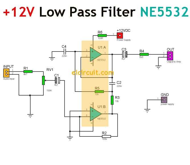
Simple 12V Low Pass Filter NE5532 - Electronic Circuit

Passive Band Pass Filter Circuit Diagram
